Single-Sided Layout


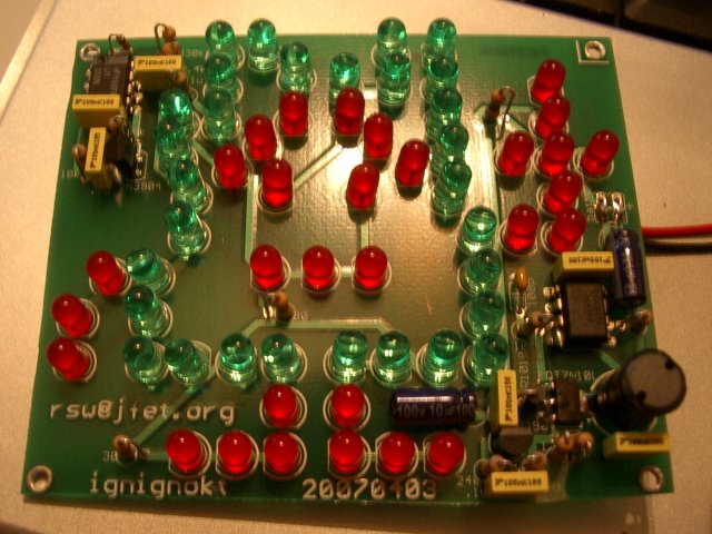
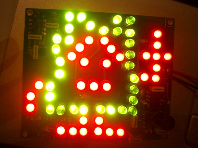
By now everyone's heard about the 2007 Boston Mooninite Scare. Unfortunately, as far as I know, no one has put any thought into mass producing more of these guys. Well, no more. Thom, a now-buddy of mine from Chicago, emailed me after he saw my Superbowl party window decoration to tell me that he thought it would be awesome to design a Mooninite PCB that could be built cheaply enough to be used as a throwie. So here it is.
Admittedly, there was another factor that encouraged me to build these, namely, MIT's Campus Preview Weekend, when dorms "rush" the incoming freshmen. Some residents of my former dorm (and in particular, Fort Awesome) were looking for ideas for a cool activity to expose the prefrosh to the kind of in(s)anity that's regularly perpetrated, and we came to the conclusion that a "soldering clinic" culminating in the creation of a Mooninite throwie would be badass.
So why do you care? Well, the most interesting part of the whole thing is the dc/dc converter, the design for which I will soon fork into a standalone project, but in general this design is an exercise in absolute minimum cost, and I think in the end you'll agree we've achieved that here.
LEDs are easy to drive, right? They have a (more or less) fixed forward voltage, so in principle you just have to give them a current limiting resistor and off you go. In practice, however, running lots of LEDs off a low voltage source becomes very wasteful. Imagine, for example, that I'm trying to drive 16 LEDs, each with a 2V forward drop, from four AA batteries (6V). That means I have to have 8 strings of 2 LEDs (4V each) plus 8 resistors, each of which has 2V across it. (Yes, I could just parallel up five chains of three in series, but this gives very unpredictable current through each chain, meaning that the brightness won't be uniform across the chains; moreover, this is a recipe for disaster, since LEDs suffer from the same thermal runaway problems as BJTs or any junction device. Thus, while this idea looks good on paper, in practice it's not at all feasible).
For a given current I through the LEDs, I have 32*I watts dissipated in the LEDs (producing light) and 16*I watts dissipated in the resistors (wasted), meaning that I'm only utilizing 67% of the power I'm drawing from the battery! Moreover, as the battery discharges, its output voltage droops, which causes the LEDs to grow dimmer and dimmer.
So what are we trying to do? Let's build a circuit that will give us constant light output no matter what voltage the battery is producing, and which will not require us to burn lots of power in resistors. How? The latter can be achieved by increasing the number of LEDs per chain, which reduces the number of resistors in the circuit but requires that we boost the input voltage to something higher. Aha! Now we just need a feedback controller so that the voltage to which we boost is constant. Thus, our goal is to design a boost converter which regulates the current through our chains of LEDs.
There are lots of boost converter controllers out there. One of the cheapest and most popular is the MAX1771, but even this "low cost" controller is more than $2 in hundred quantities, and still requires another dollar or so worth of parts to fill out the rest of the regulator. We can do much better than this.
When designing for absolute lowest cost, I've learned that the first question I should ask myself is "can I do this with a 555?" The reason can be summed up with this simple fact: in 2003 alone, more than a billion of these little bastards were made. That's right—the 555 has outsold every other IC in history, and huge volume equals low low cost.
I've preliminarily written up the resulting design, now called Inara, but fear not! a neater (read: not hand-written) writeup is forthcoming.
Meanwhile, let's compare the cost of this solution to one employing the MAX1771. Both require the switching core of the converter:
dc/dc BOM (need for both designs):
        FQT7N10L        $0.1609
        SR1010 diode    $0.12
        390uH inductor  $0.375
        10uF 100V cap   $0.0428
        100uF 16V cap   $0.0397
        .1uF 100V cap   $0.0362 x2
        .5 Ohm resistor $0.0076
dc/dc BOM total         $0.8184
The MAX1771 requires a couple external components to set up the switching frequency et cetera:
MAX1771                 $2.15
        100pF cap       $0.0378
        feedback R      $0.0038 x2
        .1uF cap        $0.0362
MAX1771 total           $2.2316
Inara requires quite a few parts, which admittedly does take up board space. However, if you look at the layouts below you'll find that the size of the board is dictated exclusively by the size of Ignignokt himself, so the additional board space doesn't actually add any cost. The parts cost is as follows:
inara
        2N3904          $0.02792 x2
        SE555           $0.168
        LM358           $0.189
        100pF cap       $0.0378
        resistors       $0.0038 x13
        .1uF bypass     $0.0362 x5 (could go with fewer...)
        1N4148          $0.0132
inara total             $0.69424
So that's a 3.2x cost reduction for the controller, which translates to a 2x cost reduction for the whole dc/dc converter. Not too shabby!
So now we have this dc/dc converter and we're ready to hook everything up, but wait! I really want to be able to drive two colors of LEDs, one for the body and one for the face/hands/feet. The apparent problem is that this requires driving chains of different colored LEDs, which don't necessarily have the same forward drop. Fortunately, we can be a little sneaky in the way we chain together the LEDs and make this a nonissue.
Consider: if I have two chains in parallel, each of which is a mix of two or more different types of LEDs, as long as each chain has the same makeup, they will have the same sum of forward drops. This means I can get away with using a mix of LEDs as long as each parallel chain has the same number of each color. In this particular design, I've got 60 LEDs total, 30 of which make up the body and 30 of which make up the face/hands/feet. Since I decided to have three chains of 20 LEDs each, I just have to be sure that each chain has 10 of the body LEDs and 10 of the others. Best of all, since I designed the converter to regulate the current through the chain as opposed to the voltage across it, I don't even have to specify what colors of LED I'm going to use—as long as the body LEDs all match one another and the face/hands/feet all do as well, I can do whatever I want (provided I don't use insanely high forward drop LEDs that cause my output voltage to exceed the voltage ratings of the devices in the converter, that is).
Painstakingly laying out an image in LEDs is not my idea of a fun Sunday afternoon. On the other hand, writing scripts to do it for me sounds like a blast!
...so that's what I did. The script, coords.pl, takes in a set of coordinates and puts out one of two scripts, either the "add" script (used in the Eagle schematic editor) or the "move" script (run in the layout window after the "add" script has been run to generate the schematic).
Unfortunately, you need a non-freeware copy of Eagle to run a script that can add parts to a schematic. On the other hand, it shouldn't be hard to modify the perl script to instead generate an Eagle script which will add holes in the right spots in the layout, which I believe is supported by the freeware version of Eagle.
If you plan on manufacturing your own, you'll need either the Gerber files (zip) or the schematic and layout (pdf). The former should be ready to upload to board houses such as Advanced Circuits, Sunstone, Imagineering, or PCBCart, all of whom I've employed successfully for PCB manufacturing in the past.
Single-Sided Layout

If you prefer to manufacture the boards yourself at home, you will likely find the single-sided layout more to your liking. The circuit is identical to the above; I've just changed the way that it's wired so that it uses almost exclusively one side of the board. There are still 8 jumpers required (see the short blue segments in the picture to the right), but for most of them you can just bend a component lead around and solder it again. The trace width and spacing are both 15 mils, so you shouldn't find the etching too difficult.
If you're not familiar with home etching, there are several good pages to consult.
Note that the components should really be on the same side as the copper, but with the exception of the DIPs and the 2N3904s, you can get away with flipping them over to the other side of the board to make soldering easier. Also, the pads for the LEDs are different shapes to differentiate anode (positive side, long lead, round edge of LED, octagonal pad) from cathode (negative side, short lead, flat edge of LED, rectangular pad). This should make stuffing easier and less error-prone.
The BOM is as follows, including Digi-Key part numbers:
Passives
--------
390uH, 780mA inductor	1	M8635-ND
100pF, 16V cap		1	BC1013CT-ND
100uF, 16V cap		1	P5138-ND
10uF, 100V cap		1	P5309-ND
.1uF, 100V cap		7	478-3379-ND
10k Ohm resistor	5	10KQBK-ND
30 Ohm resistor		3	30QBK-ND
1 Ohm resistor		2	1.0QBK-ND
470 Ohm resistor	1	470QBK-ND
24k Ohm resistor	1	24KQBK-ND
1.6k Ohm resistor	1	1.6KQBK-ND
30k Ohm resistor	1	30KQBK-ND

Actives
-------
2N3904 NPN transistor	2	2N3904FS-ND
FQT7N10L N-chan MOSFET	1	FQT7N10LTFCT-ND
NE555 timer		1	LM555CNFS-ND
LM358 dual op-amp	1	296-1395-5-ND
SR1010 Schottky diode	1	SR1010-TPCT-ND
1N4148 diode		1	568-1360-1-ND
5mm red LED		30	160-1087-ND
5mm green LED		30	160-1131-ND

Other
-----
9V battery clip		1	BS6I-ND

