
Apparently I'm in the shameful habit of making clocks in my spare time. First it was the Weston voltmeter clock, and then "Nixie 1," a single-digit Nixie clock. Since soon after finishing the latter, I've been daydreaming about making a clock out of an electrostatic deflection CRT—the kind of thing you find in an oscilloscope. Given that I've just come across some free time in the form of Christmas vacation 2005, I decided to make one of my own.
A few other people have made these clocks as well.
In addition to the above, I gleaned valuable information from the following:
As I've recently found, it's not all that easy to find information on electrostatic deflection CRTs. Most large CRTs are magnetically deflected, which limits the speed at which the deflection can be varied because of the large inductance of the deflection coils. Scope CRTs, on the other hand, utilize electrostatic deflection because it gives a much faster deflection circuit (since the deflection plates are essentially a 10ish pF capacitor). Electrostatic CRTs are generally pretty small—I believe the largest ever made was around 10 inches—and I've never heard even the slightest whisper about anything but monochromatic electrostatic CRTs.
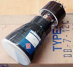
The figures of merit with regard to electrostatic CRTs are anode potential, focusing potential, brightness potential, and deflection sensitivity. Most CRTs can take a fairly wide range of anode voltages; the higher the anode potential, the greater the velocity of the electrons. This has two effects: it makes the dot sharper, and it decreases the deflection sensitivity (since the electrons spend less time between the plates, they are accellerated for a shorter period of time, and thus aren't deflected as much). The CRT that I'm using is the Telefunken DB7-12C, the specifications of which are as follows (from Franz Hamberger's database):
|
|
|
|
|
The above data reflect operating characteristics of the DB7-12C at two operating points, 800V and 2kV. As we expected, deflection sensitivity and beam width both decrease with increasing anode voltage.
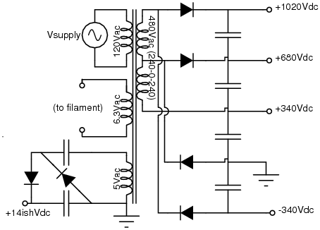
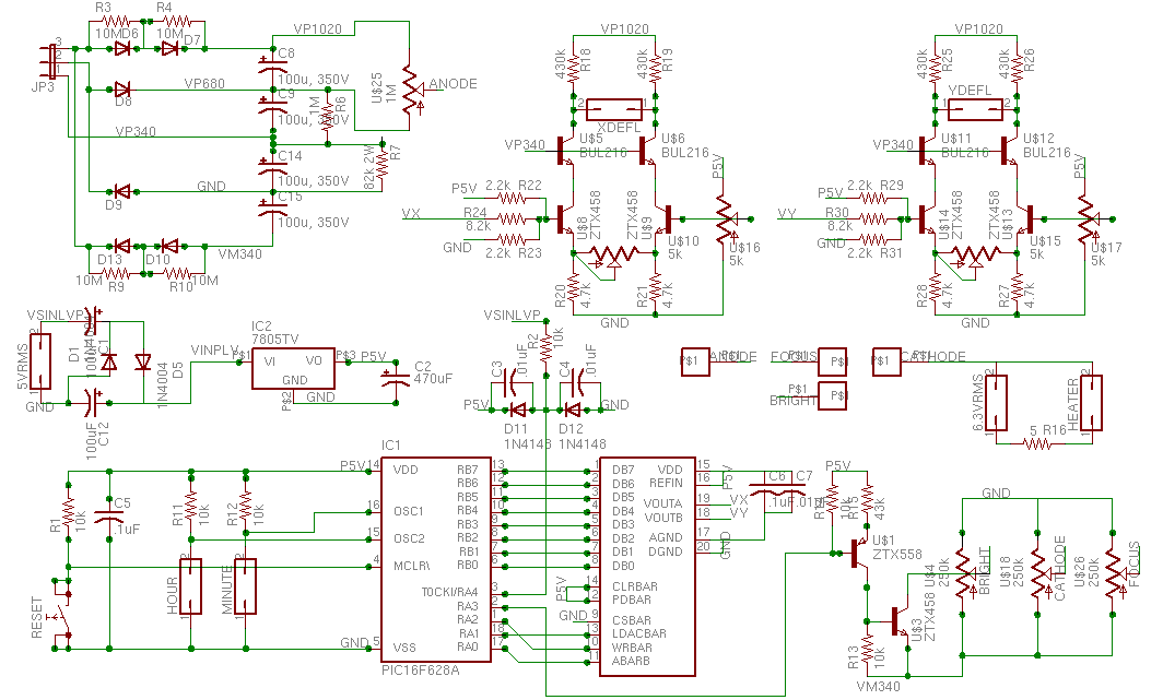
My biggest limitation in designing the CRT driver was finding a transformer for the power supply. Fortunately, Hammond Manufacturing produces a line of high voltage trafos which are likely to satisfy the needs of any ESDCRT power supply. In my case, since the DB7-12C filament voltage is 6.3VAC and I needed about 1200V total while still using a nice little transformer (since I'm pulling next to no current out of the thing), I chose the 270X, which will give 480VRMS with a center tap (240-0-240) at 50mA, 6.3VRMS at 1.5A (the DB7 needs a measly 300mA on the heater), and 5VRMS at 2A.
OK, let me get this off my chest right now: I love transformers. Yeah, they're big, heavy, ugly, all that. BUT, and this is big (hence the bold), you get a floating power supply. Why is this so hot? Observe! in the figure to the right, how we take advantage of our ability to reference the transformer windings arbitrarily to get exactly the potentials we want out of our power supply.
A quick rundown for the voltage doubler impaired: the high-voltage supply is more or less a couple Greinacher multipliers in parallel, one hanging off the top and one off the center tap. This produces -680, -340, 0 (the bottom tap), +340, and +680. Now we tie the -340 (relative to the bottom tap, remember) to ground, producing (now with respect to ground) -340, 0, +340, +680, and +1020. We could do this without the diodes from the center tap, but doing so in this way helps ensure that the voltages split evenly between series caps. The 6.3Vac heater supply can't also be used to produce the 5V supply, since we want to hang the cathode around -240V, which means we'd have a positive 240V cathode-to-heater voltage (bad—the tube can probably only take about 150, positive is worse than negative, and we'd rather just use a different trafo winding and make it zero). The 5V supply is derived from a 7805 hanging on the 5Vac tap, but 5Vac (=7Vpk) isn't enough for a comfortable dropout margin on the 7805 (2V, according to the datasheeet). Thus, we employ another doubler, the Villard or Cockroft-Walton, to get something like 13V (after the diode drops). Hooray for stupid diode/cap tricks.
Given our high-tension supply, we can afford to give the tube about 1150 Volts anode to cathode. This gives us some overhead for pulling the control grid low enough to turn off the beam (75V or more) and for the drop across the load resistors of the deflection amps. The various grids can be biased through potentiometers of a mega-Ohm or so, given that we can count on the grids sinking no more than a few tens of micro-Amperes (also remember that using a pot as a voltage divider from a low-impedance voltage source gives a Thévenin equivalent resistance of at max R/4). The cathode, focus, and control grid potentials fall comfortably between ground and -340V, and the anode bias and deflection plate common-mode voltages lie between +680 and +1020 Volts (though the latter is produced by the tail current through the deflection amplifiers diff pairs across the load resistors, not by a separate potentiometer). For the DB7-12C, I've had good luck with biases around -220, -230, and -140 Volts for the cathode, control, and focus potentials, respectively.
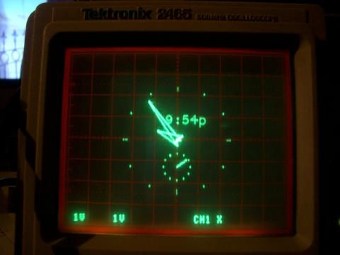
Well, the whole apparatus is useless unless we can actually make the CRT say something. That's where the deflection and blanking amps come in: we have to move that friggin beam around, and that requires some relatively serious voltages.
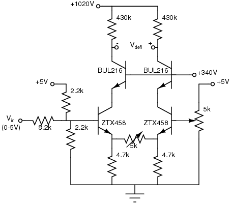
In general, it's hard to find a decent transistor that can handle lots of voltage. Most of the crud you find on Digi-Key that can handle a kilo-Volt or more is designed for some really massive current switching, not for a diff amp. About the best transistor cheaply available that can handle a reasonable amount of voltage is the ZTX458, which, despite its 400V VCEo rating, still has reasonable speed (50MHz fT) and β (200). Now, we could move the biases around such that the deflection transistors only had to stand off about 400 Volts, but that would limit the total amount of available deflection to a couple hundred volts differentially. Since I wanted to be able to play around with higher-voltage CRTs in the future, I decided to add cascodes ("all I'm proposing is that we add a little complexity!") to stand off a higher voltage. The BUL216 can handle about 800V VCEo, but its β is crappy (20ish) and it isn't terribly fast. That's OK, though; it'll do its job, viz., standing off a whole lot of voltage, just fine. Here, Matilda, we see the beauty of the cascode: we combine two mediocre transistors into a burly beast.
The potentiometer between the emitters of the signal transistors controls the gain of the circuit. As the resistance is lowered, the differential gain goes up. In essence, the pot and the emitter resistor form a voltage divider which drives the emitter of the ZTX458 on the right in phase with the input voltage. Thus, the left side output is inverting, and the right side is non-inverting, giving a poor man's single ended-to-differential converter. The common-mode voltage moves around a little bit, but for our purposes, that doesn't matter much. OK, so maybe it causes a little astigmatism, but only to the extent that the focus or beamwidth changes with deflection plate common-mode potential (i.e., not much at all).
The blanking "amplifier" really just acts to shift the blanking logic level to the -340V rail, pulling the control grid to the most negative voltage in the circuit and turning off the electron beam.
OK, now we get to the part where all you digital types sigh in relief. From here on, the snarly analog mane will be shaved and swept under the carpet, and we shall interface to the CRT through the magic of an Analog Devices AD7302 DAC. The AD7302 puts out 0-5V (fancy that—the same as our deflection circuits take), provides its own internal reference, swings rail-to-rail, and works swimmingly. Along with a Microchip PIC16F628, we have ourselves a usable little graphics controller. As in my previous clocks, counting 60 Hz is the only way to go, since we already have it on the board and it saves us using a crystal oscillator.
The font coordinates I used for the numbers, letters, and symbols are based on the Hershey fonts. I played around with them enough to figure out how many points I needed for each letter, did some adjustments to compensate for the quantization problems displaying on a tiny portion of an 8-bit address space, and came up with a reasonable set of points. The next problem involved how to display the bastards. The PIC is rather annoying in that it's a Harvard architecture and it has extremely limited data storage space, so I store the point data in codespace in between calls to update the screen. It may not be the most efficient way of doing it, but it's efficient enough that I can fit everything I need in there.
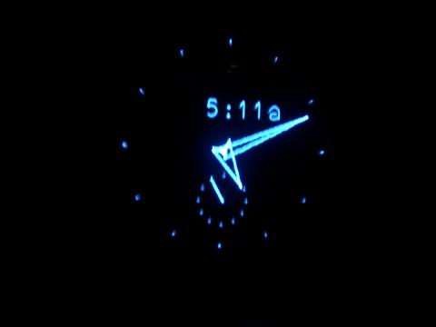
8 bits isn't quite enough resolution for the analog clock face, so I fake a 9-bit number by storing the bottom 8 bits and figuring out the ninth based on the hand position (12 minutes must be in the first quadrant, 37 minutes must be in the third, &c). Moreover, I get half-minute angular resolution by interpolating between the points in the lookup table. By the way, this lookup table is the real thing—using the data EEPROM, which has just about as much storage space as I need. I generate arrows by following a path defined by angles relative to the present hand position. Since I'm able to draw using an arbitrary center point, I can use this same table to generate the smaller face with the seconds hand.
The refresh rate is governed by the mains frequency—each cycle generates an interrupt, which updates the counts appropriately then kicks off a write cycle. When the write cycle is done, the PIC busywaits until the next interrupt. This gives us a mains-synchronized 60Hz refresh rate, which keeps the image from swimming in the presence of strong mains-coupled magnetic fields. Nevertheless, it's still worthwhile to shield the CRT: synchronizing the refresh with the incident magnetic field means that we're essentially aliasing the distortion from 60Hz to DC—a fancy way of saying that instead of swimming, it'll just look out of whack. If your CRT doesn't have its own shield, Advance Magnetics will gladly sell you several square feet of high- and low-permeability foils, perfect for shielding the trafo and CRT from each other. I ended up using two layers of the 6 mil AD-MU-80 separated by a layer of duct tape, though one probably would have sufficed.
By the way, this is the first project on which I've used GPUtils. GPAsm and GPSim are both pretty damn good, and although I haven't yet taken advantage of GPAsm's ability to create relocatable objects, it does seem quite hot.
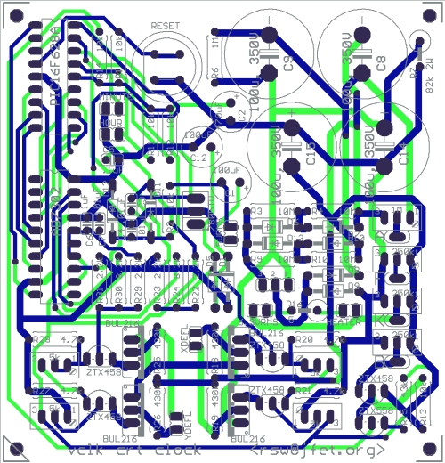
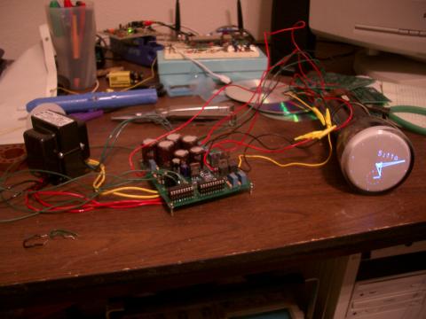
As always, Advanced Circuits made my boards. Digi-Key supplied the lion's share of the components, with the exception of the Hammond trafo, which came from STF Electronics, an great little company with fast service and excellent selection. Sphere Research sells a bunch of different ESD CRTs, one of which will certainly suit your tastes. Don't forget that you're going to want a case for all this (if only to support the CRT)—and Cases for Collectibles can supply you with a high-quality acrylic case in which to swaddle your new baby.
These gerber files are all ready for uploading to 4pcb; alternatively, have a look at the individual layers in EPS format. If you just want to burn the PIC and forget about it, here's the hex file (or a version for those with 50Hz mains). If you're interested in actually reading my code (don't send me email making fun, it'll just get binned), grab the tarball and have at it. Start with the Makefile and all will be clear.
Here's the bill of essential materials for the clock, and a few notes:
	Qty	Value			Comments		Digi-Key Part #
	---	-----			--------		---------------
Capacitors:
	3	.01uF						P4963-ND
	2	.1uF						P4924-ND
	4	100u, 350V		EKXG351ELL101MM25S	565-1457-ND
	2	100u, 15V					P1180-ND
	1	470uF, 15V					P10274-ND

Resistors:
	1	5 Ohm, 2W					PPC5.1W-2CT-ND
	1	200 Ohm, 10W					200W-10-ND
	4	2.2k Ohm					2.2KQBK-ND
	4	4.7k Ohm					4.7KQBK-ND
	2	8.2k Ohm					8.2KQBK-ND
	6	10k Ohm						10KQBK-ND
	1	43k Ohm						43KQBK-ND
	1	82k Ohm, 2W					PPC82KW-2CT-ND
	4	430k Ohm					430KQBK-ND
	1	1M Ohm						1.0MQBK-ND
	4	10M Ohm						10MQBK-ND

Potetiometers:
	4	5k Ohm			PV36W502C01B00		490-2888-ND
	3	250k Ohm		PV36W254C01B00		490-2885-ND
	1	1M Ohm			PV36W105C01B00		490-2877-ND

Actives:
	8	1N4007						1N4007/54GICT-ND
	2	1N4148						568-1360-1-ND
	1	7805						MC7805CT-BPMS-ND
	1	AD7302						AD7302BN-ND
	1	PIC16F628A					PIC16F628A-I/P-ND
	4	STP2NK90Z					497-4378-5-ND
	5	ZTX458						ZTX458-ND
	1	ZTX558						ZTX558-ND

Transformer:
	1	Hammond 270X

Switches:
	1	ITT D6-R-90					401-1008-ND
	2	Judco SPST					502PB-ND